Adaptive Time Stepping
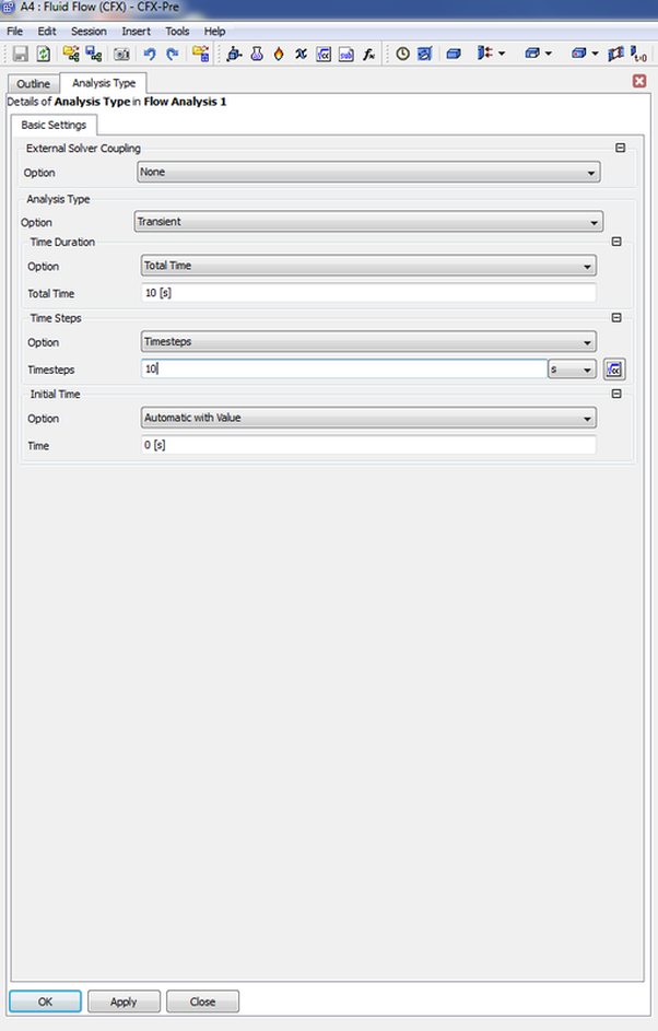
At first after selecting confirming that you can run a steady state simulation on the required mesh, the next step comes by selecting Transient under the Analysis Type Option.
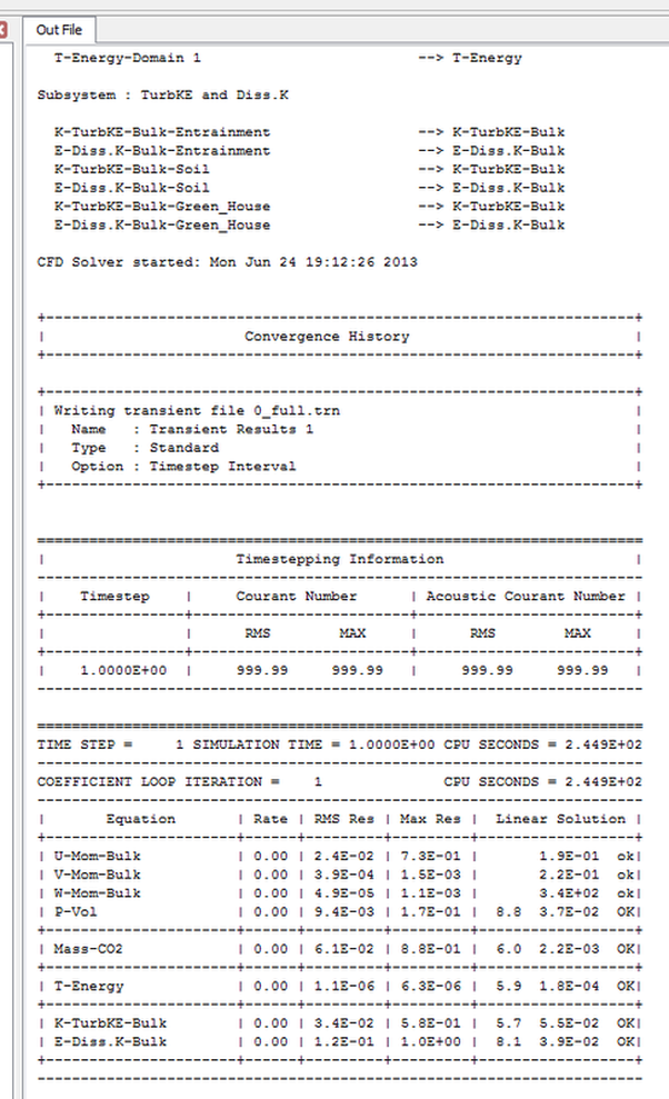
The next step after the simulation has been initiated moniter under the time stepping option the courent number you can see that there are two vlues on courent number RMS and MAX. Moniter the simulation courent values at each time step that would would allow you to chose resonable values for chossing that right values for the adaptive time stepping simulations.
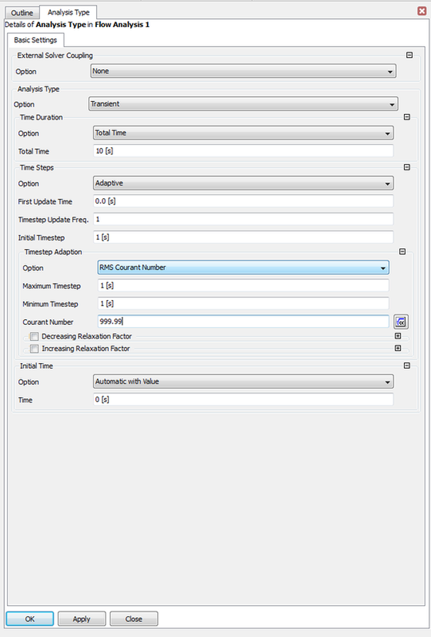
After Knowing the working cournt numbers next comes selecting the adaptive time stepping, select the follwing values shown bellow at the following picture:
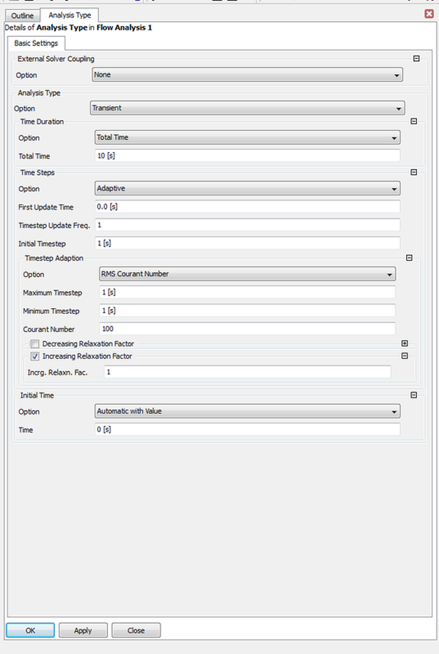
The next step is to reduce the courent number and apply a relaxation value also in order to get less fluctuations once a simulation is run and with the progression of number of iterations a more resonable output plot should be noticable.
Then comes the step in minimzing the the maximum and minimum maximum and minimum time step.
Then once you find that itterations are taking with time some sinosidal form that means in some words that you have nearly got to the required minimuam and maximuam time step what comes next is to increase the courant number.
You will need to save the the stable condition established in the stable eterations and then to use them as an intial conditions to run a new simultion.
You will need to save the the stable condition established in the stable eterations and then to use them as an intial conditions to run a new simultion.
Dynamic Time Stepping
Some times a simulation encounters different events and as an objective by the researcher is to keep it running without crashing at the same time to insure correct results are obtained.
The first question that comes to mind when do I use dynamic times stepping and when do I use static times stepping.
Example 1
As an example to get things clear, imagine that you are simulating a cyclic duration of a desil engine. Where six process are simulated the first one is the suction into the chamber then comes the spray one then compression stage then comes the combustion process then finally the scavenging process.
The six process would require different numerical stability conditions, meaning when suction ocuurs a stability condition is assigned for it to capture length scales that are related to the inflow valve length scale, Then comes the compression stage that requires a stability condition for each time step, so for a compression stage of 10 time steps where each time steps is 3micro second, the third process is the combustion process where high speeds and a sudden release of energy occurs this requires its own stability condition.
Example 2
This is when a combustion process is studies by itself.
Example 3
Something encountered in the simulation of shock-waves.
Example 4
Something encountred in the simulation of rotating fans.
|
Unless otherwise noted, all content on this site is @Copyright by Ahmed Al Makky 2012-2014 - http://cfd2012.com


