Coming Soon a Book on Aircraft Design
|
The material is available hope I get time to put it together.
The book consists of 10 chapters. The book is intended for undergraduate student. Its written to provide a hands on reference to the student. To quickly get what he want and apply it straight away to his problem of interest. Chapter 1 Aircraft Anatomy. Chapter 2 Aircraft Classification Chapter 3 Acting Forces on Aircraft Chapter 4 Wings and Lift Chapter 5 Aircraft Propulsion Chapter 6 Drag Calculation Chapter 7 Weight Calculation Chapter 8 Low Speed Configuration Chapter 9 The use of CFD Chapter 10 Wind Tunnels Chapter 11 Lift Enhancement Chapter 12 Flow Control Praying that this book can contribute to the development of all students out there who love flight. And to whom who seek a future in that area of science.
|
 |
The Design Process
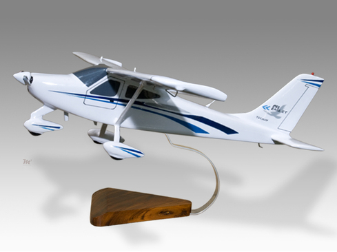
Aircraft design goes through numerous development stages. Usually it starts with specified requirements set by the ministry of transport for a civil aircraft or the ministry of defense would set the requirement for a jet fighter. Drawings are made and several design concepts are chosen. The designs are sent to the workshops and wind tunnel scale models are constructed. The picture below shows a constructed model click on the image to get more info about the source of the image. What is used at some instances to check the streamline flow pattern around an aircraft is through putting it in a water tank and applying dye to the flow and seeing how aerodynamically efficient it is. By following the dye stream lines flowing around the aircraft body any regions of flow stagnation can be detected at different flow regimes.
Wind tunnel tests are done for the following
1-To calculate the drag coefficients at different flow velocities and also to measure the drag force generated during flight.
2- Seeing the shock waves occurring to sonic and supersonic flow regimes. By seeing the shock waves and how they interact with various parts of the aircraft, the importance of this comes from seeing how control surfaces get affected by these flow patterns. Losing control of an aircraft comes from control surface not performing their role.
3- Flutter tests, that is through exposing the model aircraft to its extreme flight conditions it is designed for.
4- Seeing the generated lift the plane makes at different pitch angles, again the selected wing profile depends on the design specifications and requirements. Meaning the wing profile used for a jet fighter will be different than the one used for a civil airliner.
Then the designers use dimensional analysis to make estimates of the generated lift of a full scale aircraft model in addition to estimating the generated drag for a full scale model.
Once this is done the design stage can proceed to the radio controlled flying model stage. Then a mock up of a full scale aircraft is done. Engine selection occurs during this stage. Then comes weight distribution of different components spread out in the aircraft structure having in mind that it doesn’t affect the control of the aircraft. Then comes selecting the landing gear. The aircraft structure detail comes next and this is when different parts manufacture comes in hand. Meaning the different fuselage sections to be made, in addition to the construction of the wings. Flight tests then come next.
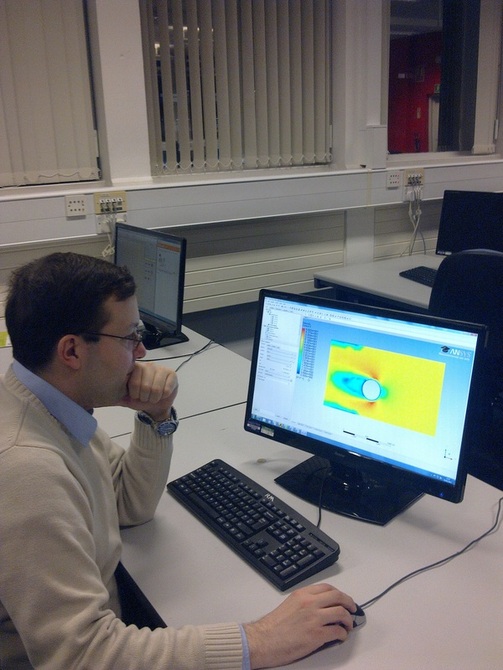
The use of CFD software instead of running any wind tunnel tests.
Understanding Aircraft General Characteristics
The following example is the general characteristics of Sukhoi Su-24, these kinds of sets of data give a quik summary about the aircraft:
Performance
Will add the required definitions for each parameter. Example:
Manufacturer's empty weight (MEW), also known as Manufacturer's weight empty (MWE) is the weight of the aircraft "as built" and includes the weight of the structure, power plant, furnishings, installations, systems and other equipment that are considered an integral part of an aircraft before additional operator items are added for operation.
Basic aircraft empty weight is essentially the same and excludes any baggage, passengers, or usable fuel. Some manufacturers define this empty weight as including optional equipment, i.e. GPS units, cargo baskets, or spotlights.
- Crew: Two (pilot and weapons system operator)
- Length: 22.53 m
- Wingspan: 17.64 m extended, 10.37 m maximum sweep
- Height: 6.19 m
- Wing area: 55.2 m²
- Empty weight: 22,300 kg
- Loaded weight: 38,040 kg
- Max. takeoff weight: 43,755 kg
- Powerplant: 2 × Saturn/Lyulka AL-21F-3A turbojets
- Dry thrust: 75 kN each
- Thrust with afterburner: 109.8 kN each
- Fuel capacity: 11,100 kg
Performance
- Maximum speed: 1,315 km/h (710 kn, 815 mph, Mach 1.08) at sea level; Mach 1.35 (1654 km/h) at high altitude
- Combat radius: 615 km in a low-flying (lo-lo-lo) attack mission with 3,000 kg (6,615 lb) ordnance and external tanks ()
- Ferry range: 2,775 km
- Service ceiling: 11,000 m
- Rate of climb: 150 m/s
- Wing loading: 651 kg/m²
- Thrust/weight: 0.60
- G-force limit: 6 g
- Takeoff roll: 1,550 m
- Landing roll: 1,100 m
Will add the required definitions for each parameter. Example:
Manufacturer's empty weight (MEW), also known as Manufacturer's weight empty (MWE) is the weight of the aircraft "as built" and includes the weight of the structure, power plant, furnishings, installations, systems and other equipment that are considered an integral part of an aircraft before additional operator items are added for operation.
Basic aircraft empty weight is essentially the same and excludes any baggage, passengers, or usable fuel. Some manufacturers define this empty weight as including optional equipment, i.e. GPS units, cargo baskets, or spotlights.
Some Questions, What is? and Why they are Important?
The following parameters will be described with examples. Some of these paramters come of intrest in the application of aircraft storage, others are related to ranges of operational range in the atmospher, some relate to design restrictions at different flight regimes, and some relate to pre-flight planning before taking the plane for a ride.
1-G-force
2-Thrust/weight ratio.
3-Wing Loading.
4-Rate of Climb.
5-Service ceilling.
6-Ferry Range.
7-Combat Radius.
8- Maximum Speed.
9-Usable Fuel.
10-After burner.
11-Fuel Capacity,
12-Dry Thrust.
13-Empty Weight.
14-Loaded Weight.
15-Wing Area.
16-Wing span.
17-Max takeoff weight.
18- Power Plant.
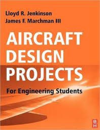
Recommended Reading List
This is a helpful book (AIRCRAFT DESIGN PROJECTS) for undergraduate students working on an aircraft design project (final year project)for the first time. it has lots of explanations and be of good help throughout the calculation process of the project
This is a highly recommended book ( GENERAL AVIATION AIRCRAFT DESIGN) take my word for it (completely not a waste of money) straight to the point with the addition to new up to date material about new trends used in aviation
Mathematical Modelling Side
The last chapter in the book on Aircraft structures by Megason covers some theory about aero elasticity.
1-You need to gather some initial parameters for your case. The first is the flow speed the aircraft will encounter at the maximum flight regime it can encounter.
2-Then you will need to get all the geometrical dimensions relating to the wing aerofoils you will be studying.
3-Modelling the geometry using a CAD software comes next.
4-Then unsteady simulations are required to be run on the aerofoils at the critical flow velocities the wing would encounter.
5-Specifying the regions of high force affecting the surface comes next and plotting the force distribution in the wing span direction and the camber direction is required.
Using CFD for Design Validation
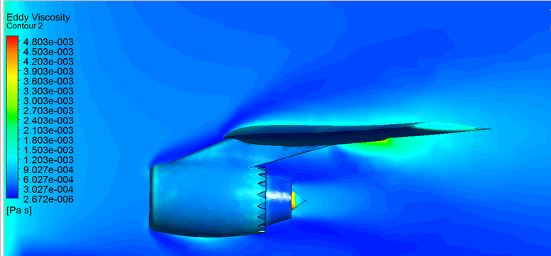
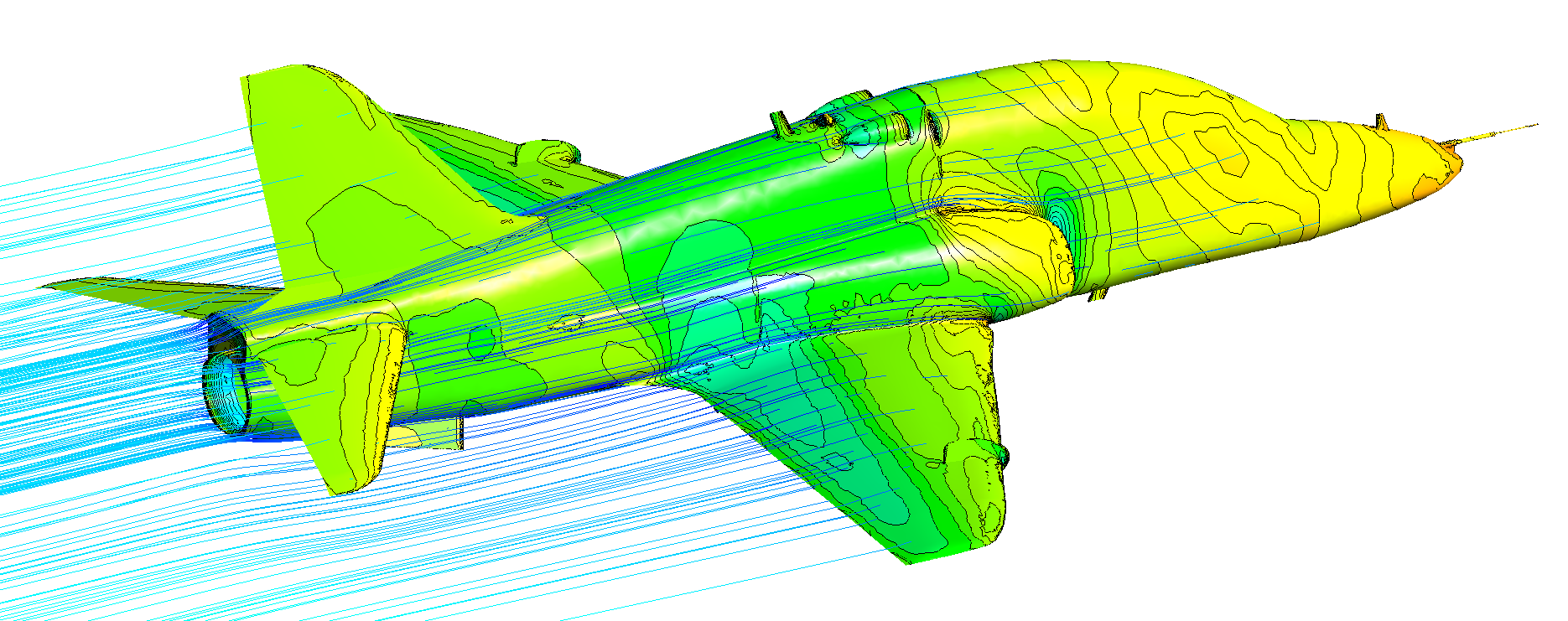
Identifying the regions of flow dissipation using the Eddy viscosity parameter at different locations, as can be seen the rate of dissipation is large at regions of after the wing and engine. Eddy viscosity is the transfer of momentum with turbulent vortcies.
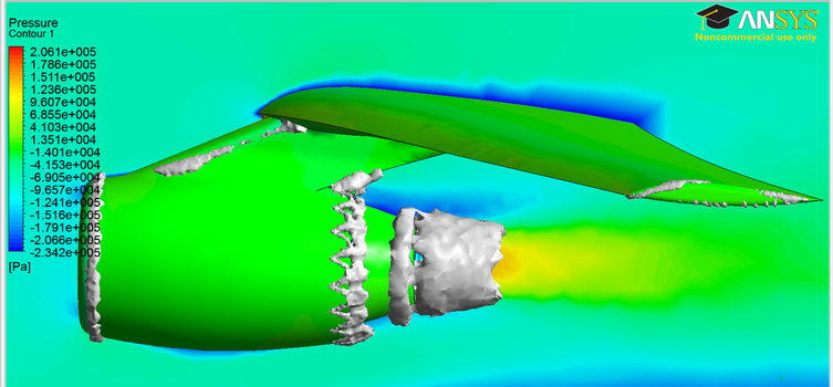
Locating regions of high turbulence can be seen through the white clouds at different regions, these are the ones of flow speed up such as the wing tip, the jet engine intake and the plyon connecting the engine with the wing.
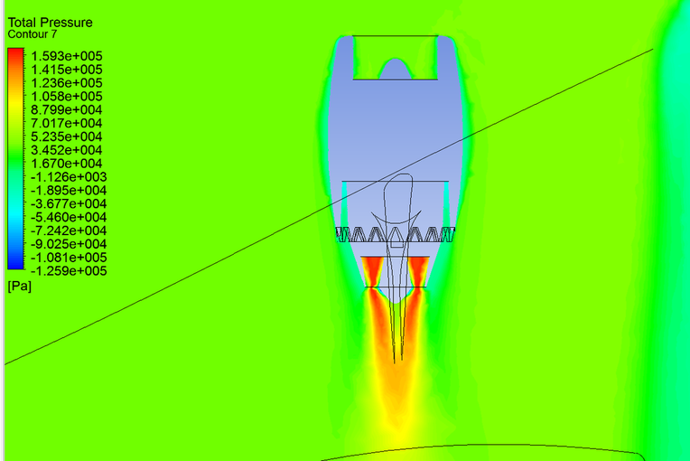
Using the CFD to visualize the bypass flow from the turbine around the exiting jet from a jet engine.
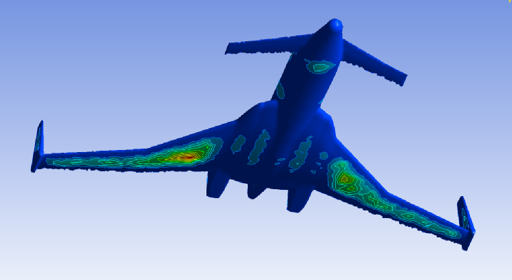
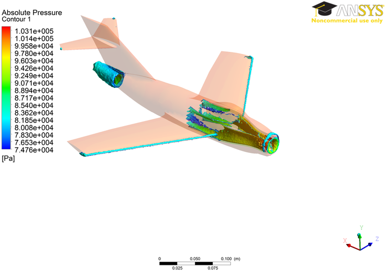
Locating the lift force contours acting on the surface of an aircraft
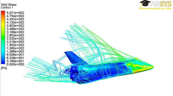
Using CFD to locate the regions of highest shear stress on the aircraft surface for the following picture it was used to verify that the rear end of the aircraft is being protected from thermal effects during re-entry in addition to the protection of the flight cabin area.
Computational fluid dynamics can also be used to introduce new concepts such as the following one for helicopters
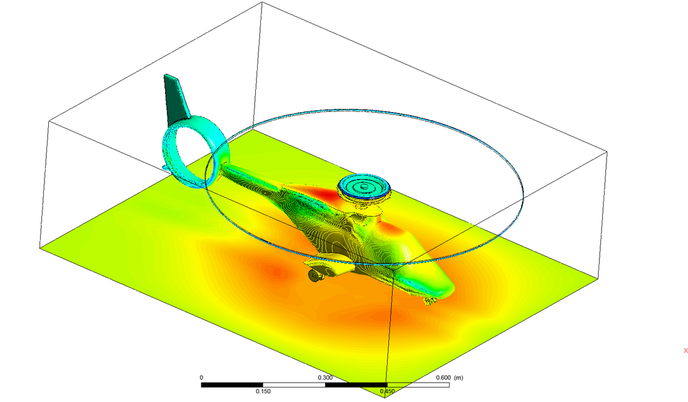
Using smoke to see the generated mass flow rate produced by the helicopter blades.
Specefying regions of high pressure mostly visible in red, as can be seen for the BAE-HAWK model.
The power of CFD is shown in this video applied for an aerospace application
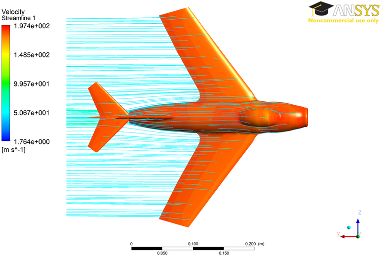
Using a CFD simulation to see the aerodynamic efficiency of the Mig-15 design, by following the streamlines coming off the aircraft surface an assessment of the design can be done.
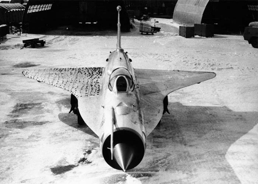
The following picture taken for a Mig-21 delta wing prototype shows the use of something very much similar to feathers on the left hand wing to visualize the air flow patterns occurring on the aircraft surface during flight at different flight regimes. These flight regimes where pr-planned before flight then cameras where used to recored occuring patterns during flight to be analyzed after flight.
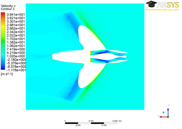
Using CFD software to visualize regions which are uneasy to access such as the flow pattern inside the jet engine intake tunnel, where in a real life example in a wind tunnel its not easy to use PIV to capture the flow pattern inside the wind tunnel.
Under construction.
Aircraft Modelling Steps
This is an initial step more details will be added soon.
1- Making a full solid model of the aircraft.
2- Modelling the movable surfaces of the aircraft.
3- Next is to specify how the aircraft is put togather.
2- Modelling the movable surfaces of the aircraft.
3- Next is to specify how the aircraft is put togather.
4- Conducting Boolean operations to separate the nose section from the fusaladge, tail, wings.
5- Modelling where the conecting bolts are specified to link the different sections.
6- Modelling the connecting ribs for each section.
7 Saving each part speratly and working on the details independently.
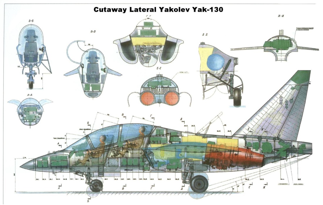
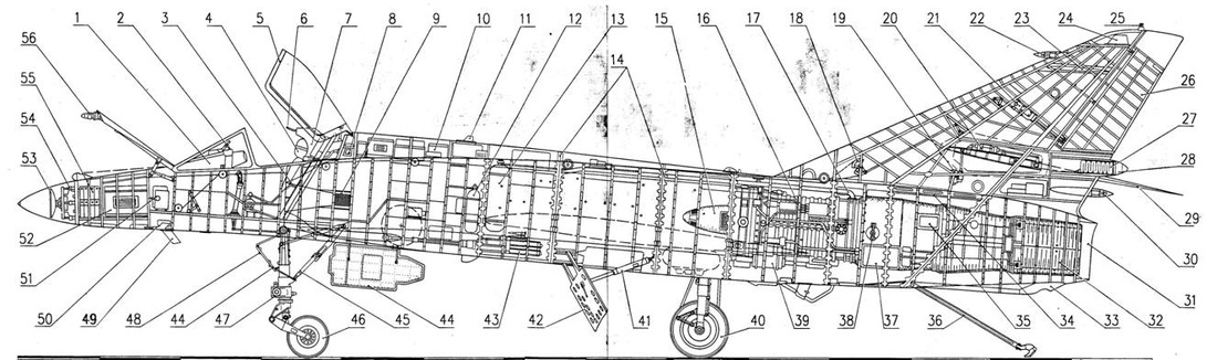
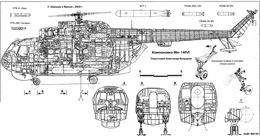
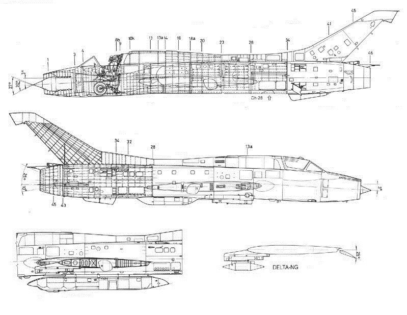
There are lots of useful images online showing the internal distribution in the cross sections. To model the exterior you just require cross sections, while to start modelling the interior you will need images like the one below:
The importance of these plots is that they show also the angles of inclinations for the control surfaces of aircraft, as shown in the following image for the main wing and the rear stabilizer.
Unless otherwise noted, all content on this site is @Copyright by Ahmed Al Makky 2012-2015 - http://cfd2012.com