Controlling Airfoil inflow Parameters
The latest new section on my website is the throttle valve one.
Important notes
1- Please don’t send me an email asking me to send you tutorials, what is available has been uploaded on the website.
2- I would very much appreciate any feedback about the tutorials, and your contribution will be stated in the tutorial, I plan to update the tutorials.
Important notes
1- Please don’t send me an email asking me to send you tutorials, what is available has been uploaded on the website.
2- I would very much appreciate any feedback about the tutorials, and your contribution will be stated in the tutorial, I plan to update the tutorials.
Steps of Modelling and Selection Criteria
I provide the steps required for you to trace the airfoil profile in SolidWorks:
http://cfd2012.com/uploads/3/5/1/0/35107563/tracing_pictures.pdf
After that you can just selected the profile contour entrained in the fluid domain and use the extrude command. I have a simple tutorial for ANSYS-CFX design modeler to create the model geometry:
http://www2.warwick.ac.uk/fac/sci/eng/study/pg/students/esrhaw/introduction_to_ansys2.pdf
Regarding the airfoil of your interest you will need to specify what regions of flow velocities are of your interest. Meaning what Mach speeds will you be dealing with low speed aerodynamics or high speed aerodynamics?
What flight conditions will the aircraft encounter at Low speed landings or high wing pitch lift?
Once these factors are gathered we will see what similar aircraft encounter similar flight regimes. Then we compare their used wing profiles with what we need. Last step is we would look in publications to see any provided detailed technical diagrams of interest.
Simulating Changing Pitch Angle
Try to run a time stepped simulation and then calculate the averaged parameters of interest such as averaged produced lift. Previously you where applying a steady state simulation for an unsteady flow case. Once you see convergence in iterations at a certain point no need to run to 5000 . Inorder to save your working time. Once you have verified you can get the right results then leave it overnight running calculating.
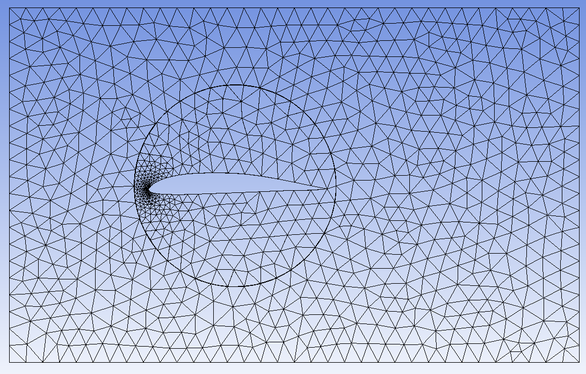
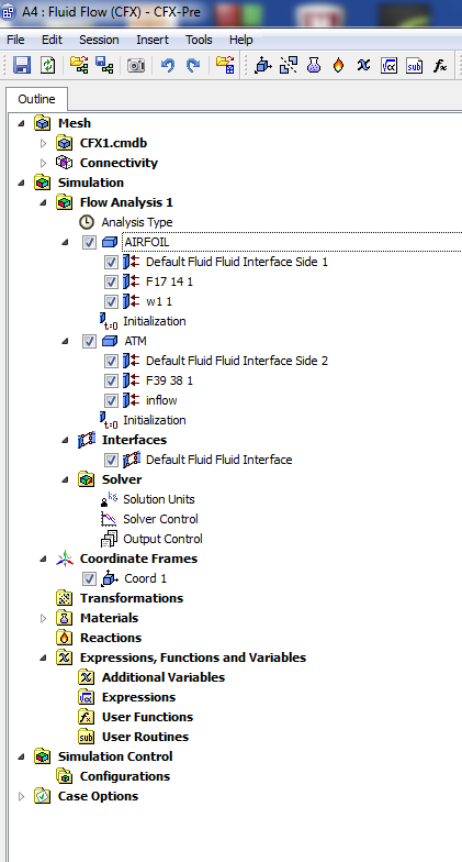
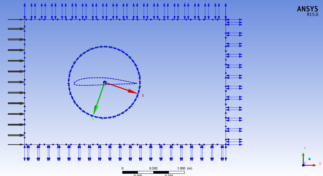
The simulation done using two domains
Step: Selecting two domains
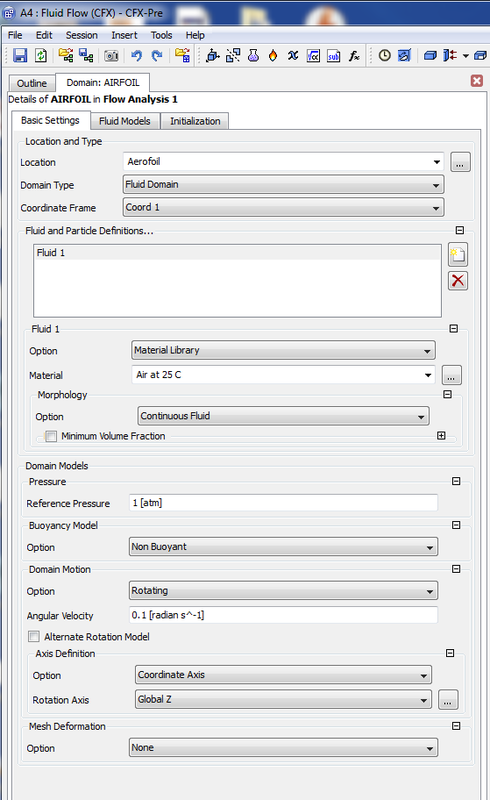
Step: Selecting rotating domain
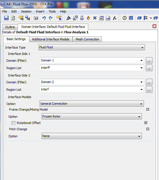
Step: Selecting Frozen rotor
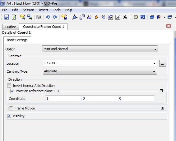
Step: Coordinate system for rotation.
Step:
An available video on YouTube about varying pitch airfoil as a function of time
Unless otherwise noted, all content on this site is @Copyright by Ahmed Al Makky 2012-2014 - http://cfd2012.com
