Flow Modelling in a Gas Turbine Combustion Chamber
This section on my website is for the gas turbine combustion chamber one.
Important notes
1- Please don’t send me an email asking me to send you tutorials, what is available has been uploaded on the website.
2- I would very much appreciate any feedback about the tutorials, and your contribution will be stated in the tutorial, I plan to update the tutorials.
Important notes
1- Please don’t send me an email asking me to send you tutorials, what is available has been uploaded on the website.
2- I would very much appreciate any feedback about the tutorials, and your contribution will be stated in the tutorial, I plan to update the tutorials.
ANSYS CFX Flow Modelling in a Gas Turbine Combustion Chamber
|
Under Construction, the material is available, unfortunately I didn’t get around writing the gas turbine combustion chamber tutorial which has been requested regularly in addition to some problems I didn’t get around in solving relating to the tutorial. Wishing you all the best.
A note to researchers who are about to take the gas turbine combustion project, its always good to know the required number of people required for a project.
The project is not easy and complex, it covers a large spectrum of challenges, this kind of expertise is only available in large companies. such a project has at least 5 people who work on it, an expert on chamber modelling and meshing, flow modelling expert, combustion modelling expert, chemical kinetics expert, fuel atomisation expert, high performance computing expert. |
 |
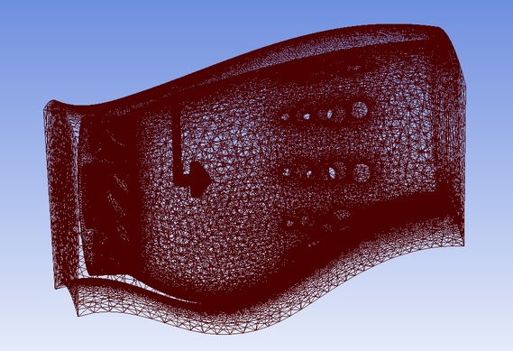
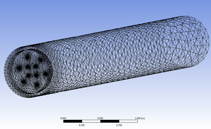
Can-Annular Combustion Chamber 1 Tutorial Geometry
To download the geometry click on the image below.
Simulation Picture Album
Chamber Required Role
Combustion is a reactive flow process. Improving combustion efficiency is through the least harming products to the environment. The improvement can be achieved with good design of combustion chambers that achieve good mixing for the fuel air mixture and avoiding having regions of high temperature which result in Nox products. This is where numerical simulation kicks in, where modelling the combustion chamber and simulating a flow through it can point out a lot of things before the manufacturing stage, its advantage is also in providing a flexible modification of the design with a wide spectrum of designs that can be chosen from. Enhancing mixing is achieved by the introduction of turbulence to the flow, knowing how to control and quantifying the process is essential due to the need to know the limits that the combustion chamber needs to work on. These processes occur in Gas turbines, steam boilers, Diesel and Gasoline engines.
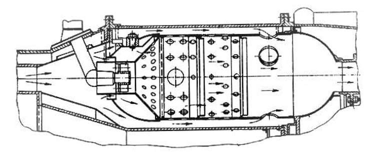
Commenting on the above image, some fundamental ideas are extracted on the needed approach to design combustion chambers.
1- Side flows are required to cool the sides of the chamber.
2- The holes provided on the side of the can is to allow the oxidizer to enter to the flame region.
3- The swirl is used to hold the flame in a focused region.
4- The inlet region of the combustion can is a divergent nozzle while the outlet section is a convergent nozzle.
5 The number of holes located on the sides of the can control the pressure difference intended for the combustion process.
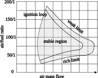
Simulation Required Values
Note: The discussed values here are just to give the researcher to what values he should be expecting while setting up his simulation or when he is conducting the data analysis part of the project.
|
1- Inflow Boundary condition, will be pure air. You will need to find out what is the flow outlet velocity from the compressors. The main inflow velocity after the compressor can be taken as 10 m/s. The secondary inflow holes relating to the dilution holes have a velocity of 6 m/s. (note that the image below is not done by me, just being used for educational purpose)
2- Outflow you will need to see from the Brayton cycle what is the maximum pressure before the turbine, then you apply it to the boundary condition. Once these values are checked then you can processed for the next stage.
|
|
3- Then you apply the mass fuel inflow to the spray, initially to simplify things study a gas fuel. For that step you need to check that you have the right volume fractions distribution for combustion. Usually you know what flow rates for air and fuel are there from the required fuel air ratio.
For a fuel spray the researcher can select a spray velocity of 40 m/s at a static temperature of 300 K. Remember to assign a volume fraction of 1 for the fuel at the fuel inflow boundary condition.
For a fuel spray the researcher can select a spray velocity of 40 m/s at a static temperature of 300 K. Remember to assign a volume fraction of 1 for the fuel at the fuel inflow boundary condition.
4- Once you are confident you have the right numbers for the simulation you can then select the total energy model. This is when you apply an inflow temperature and outflow temperature extracted from the Brayton cycle calculation. While temperature entering the combustor is 600 deg and leaves the combustor at 1400 deg.
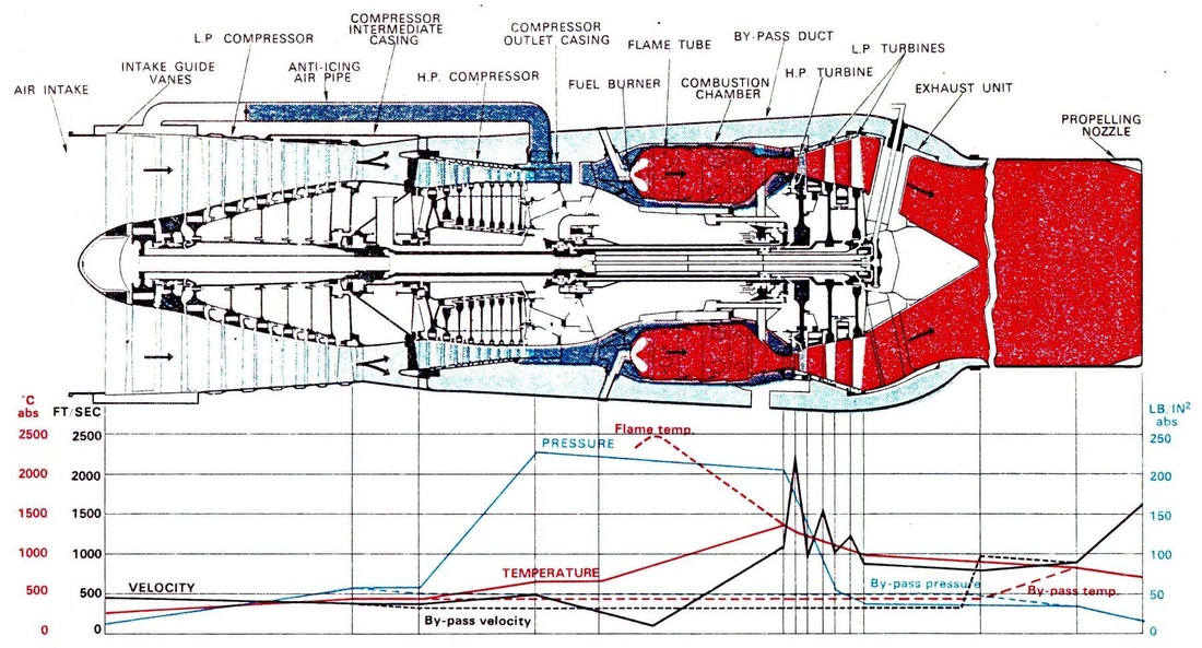
The following picture is not done by me, it is very useful for the engine design process. It is very informative and is used to show the encountered values of different thermodynamic parameters at different locations in gas turbine engine.
Commenting on the figure below the combustor inlet velocity is 500 foot/sec which is in SI units is 152.4 m/s and leaves the combustor at 457.2 m/s. Converting from FT/SEC to SI units.
Commenting on the figure below the combustor inlet velocity is 500 foot/sec which is in SI units is 152.4 m/s and leaves the combustor at 457.2 m/s. Converting from FT/SEC to SI units.
The other useful parameter is the encountered pressure at different stages of the engine, the pressure leaving the compressor is 240 IB/IN2 (1.655E6 Pa) and leaves the combustor at 200 IB/IN2 (1.379E6 Pa). Pressure converter to SI units. (note that the image below is not done by me, just being used for educational purpose)
Before we discus the adiabatic flame temperature, we need to cover its definition at two different cases:
The constant volume adiabatic flame temperature is the temperature that results from a complete combustion process that occurs without any work, heat transfer or changes in kinetic or potential energy.
The constant pressure adiabatic flame temperature is the temperature that results from a complete combustion process that occurs without any heat transfer or changes in kinetic or potential energy. Its temperature is lower than the constant volume process because some of the energy is utilized to change the volume of the system (i.e., generate work).
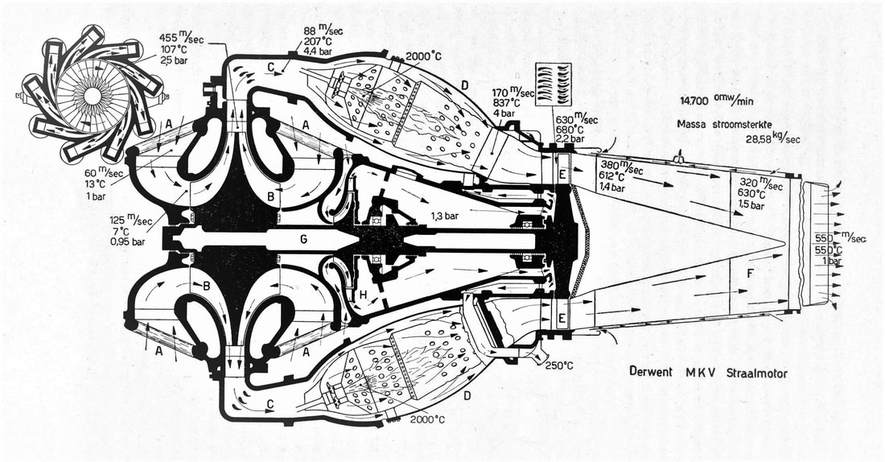
Another example case is the Derwent engine one, the image (note that the image below is not done by me, just being used for educational purpose) has all the necessary data values to give hints to the design engineer what are the expected values to be expected at different parts of the engine. By extracting the data values and by plotting them on a T-S graph what you should obtain is a Brayton cycle. Speaking of flow velocity throughout the engine, at the inlet section the air speed is 60 m/s it is speeded up before the compressor inlet to 125 m/s, it leaves the compressor at a speed of 455 m/s. The air again expands after the compressor and enters the combustion chamber at a speed pf 88 m/s. The combustion mixture leaves the combustion at 170 m/s and then the outlet converging nozzles increase the speed of the flow to 630 m/s where by it hits the turbine blades at the indicated speeds. Finally the engine outlet speed is 550 m/s. Speaking of the cooling air circuit located within the inner engine core the produced air pressure by the secondary inner compresses requires a pressure of 1.3 bar. This consequently provides the necessary airflow rate around the ball bearing fitting points to get their necessary air flux to cool down. The air temperature leaving the cooling inner engine cavities is at 250 deg.
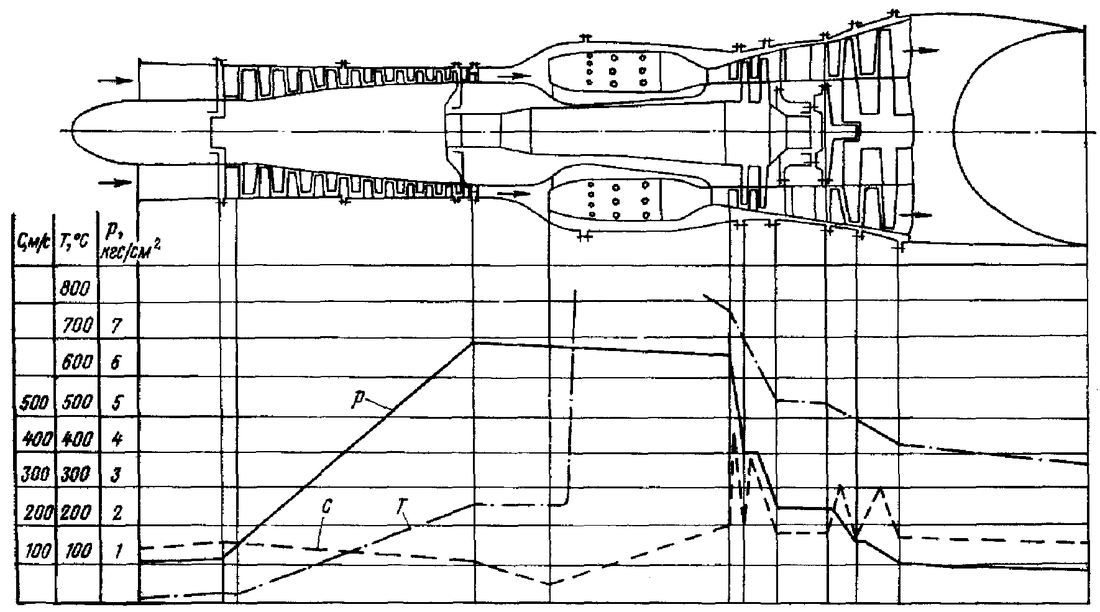
Looking at the image below (note that the image below is not done by me, just being used for educational purpose) .Steps in the design process of gas turbine engines, firstly draw the engine on paper, the next step is to make a table on the right-hand side showing all the expected values of pressure, velocity and temperature before and after each process. Then start plotting the intended values as a function of the axial length of the engine. There should be an expected temperature peak at the can combustion section. While in the compressor section there should be a rise in pressure till the end whereby the pressure is sufficient for combustion to occur.
ANSYS-CFX Unsteady Multiphase Combustion Modelling for Jet-A fuel using FlameLet
Available YouTube tutorial, a similar tutorial geometry:
1- Unsteady Simulation.
2-Assigning spray inflow regions for the fuel.
3- Monitoring the solution.
4- Loading the Flamelet library from ANSYS database and considering NOX species.
5- Applying the Jet-A fuel to the simulation.
6- Using a first order time stepping.
7- Applying the P1 radiation model.
8- Applying the particle transport fluid model.
9- Applying the thermal energy heat transfer model to the droplets.
10- Using the BVM Partially mixed Model for combustion.
11- Using the K-Epslion model.
12- Using an ignition point.
Can-Annular Combustion Chamber 2 Tutorial Geometry
To download the geometry click on the image below.
Simulation Physical Time Scale Control
Under Construction.
ANSYS-FLUENT Methane None- Premixed Combustion Modelling
The following points will be covered in the YouTube tutorial, a similar geometry:
1- Working with a Steady simulation.
2- Pressure based
3- Apply Energy equation.
4- K-Epslion equation.
5- Importing the SolidWorks geometry in Design Modeller.
6- Generating a simple mesh and assigning the required faces input and output values.
7- Applying the P1 Radiation model.
8- Using mass fraction modelling
9- Calculating the necessary combustion calculations using MATLAB.
10- Generating the PDF input file for the simulation from the species window.
11- Methane combustion therefore inlet is 1.
12- Using the cerfacs website to calculate the combustion properties like adiabatic temperature.
MATLAB Combustion Code
clc
clear
%C8H18+20(O2+3.76N2)=xCO2+yH2O+zO2+wN2
% C:
% H:
% O:
% N2:
x=8;
y=18*0.5;
z=(20*2-2*x-y)/2
w=20*3.76
NMair=20;
MAIR=29;
MC=12;
MH2=2;
mair=NMair*MAIR*(1+3.76);
NMC=x*MC
NMH2=y*MH2
mfuel=NMC+NMH2
AF=mair/mfuel
clear
%C8H18+20(O2+3.76N2)=xCO2+yH2O+zO2+wN2
% C:
% H:
% O:
% N2:
x=8;
y=18*0.5;
z=(20*2-2*x-y)/2
w=20*3.76
NMair=20;
MAIR=29;
MC=12;
MH2=2;
mair=NMair*MAIR*(1+3.76);
NMC=x*MC
NMH2=y*MH2
mfuel=NMC+NMH2
AF=mair/mfuel
MATLAB Propane Combustion Example
%First Law Combustion Analysis
clc
clear
%C3H8+7.5(O2+3.76N2)=2.7CO2+0.3CO+4H2O+28.2*N2+2.65O2
MC3H8IN=1;
MO2IN=7.5;
MN2IN=28.2;
MH2OIN=0;
MCO2IN=0;
MCOIN=0;
MC3H8OUT=0
MO2OUT=2.65;
MN2OUT=28.2
MH2OOUT=4;
MCO2OUT=2.7;
MCOOUT=0.3;
MW_Air=29;
MW_C=12;
M_C=3;
MW_H2=2;
M_H2=4;
mAir=MW_Air*(1+3.76)*7.5
mFuel=MW_C*M_C+MW_H2*M_H2
AF=mAir/mFuel
clear mAir
mFuel=0.05
mAir=AF*mFuel
%Enthalphy Values
%C3H8
hC3H8_L_F0=-118910;
%hC3H8_280K=-;
%hC3H8_298K=-;
%hC3H8_L_1500K=-;
% O2
hO2_F0=0;
hO2_280K=8150;
hO2_298K=8682;
hO2__1500K=49292;
%N2
hN2_F0=0;
hN2_280K=8141;
hN2_298K=8669;
hN2_1500K=47073;
%H2O
hH2O_F0=-241820;
hH20_280K=0;
hH2O_298K=9904;
hH2O_1500K=57999;
%CO2
hCO2_F0=-393520;
hCO2_280K=0;
hCO2_298K=9364;
hCO2_1500K=71078;
%CO
hCO_F0=-110530;
hCO_280K=0;
hCO_298K=8669;
hCO_1500K=47517;
QC3H8_in=MC3H8IN*(hC3H8_L_F0);
QO2_in=MO2IN*(hO2_280K-hO2_298K);
QN2_in=MN2IN*(hN2_280K-hN2_298K);
QH2O_in=MH2OIN*(hH20_280K-hH2O_298K);
QCO2_in=MCO2IN*(hCO2_280K-hCO2_298K);
QCO_in=MCOIN*(hCO_280K-hCO_298K);
QC3H8_out=0;
QO2_out=-MO2OUT*(hO2_F0+hO2__1500K-hO2_298K)
QN2_out=-MN2OUT*(hN2_F0+hN2_1500K-hN2_298K)
QH2O_out=-MH2OOUT*(hH2O_F0+hH2O_1500K-hH2O_298K)
QCO2_out=-MCO2OUT*(hCO2_F0+hCO2_1500K-hCO2_298K)
QCO_out=-MCOOUT*(hCO_F0+hCO_1500K-hCO_298K)
Qout_Total=QC3H8_in+QO2_in+QN2_in+QH2O_in+QCO2_in+QCO_in+QC3H8_out+QO2_out+QN2_out+QH2O_out+QCO2_out+QCO_out
Mass_Flow_Rate=0.05;
Qout=(Mass_Flow_Rate*Qout_Total)/44
Simulation Check List
1- You will need to check what combustion products will the numerical model give you in relation to your experimental data.
2- You can check if it’s the adequate model by comparing your experimental data output with the numerical simulations output.
Check: https://confluence.cornell.edu/display/SIMULATION/FLUENT+-+Partially+Premixed+Combustion
https://confluence.cornell.edu/pages/viewpage.action?pageId=262013947
https://confluence.cornell.edu/display/SIMULATION/Partially+Premixed+Combustion+-+Geometry
https://confluence.cornell.edu/display/SIMULATION/Partially+Premixed+Combustion+-+Mesh
https://confluence.cornell.edu/display/SIMULATION/Partially+Premixed+Combustion+-+Physics+Setup
https://confluence.cornell.edu/display/SIMULATION/Partially+Premixed+Combustion+-+Numerical+Solution
https://confluence.cornell.edu/display/SIMULATION/Partially+Premixed+Combustion+-+Numerical+Results
https://confluence.cornell.edu/pages/viewpage.action?pageId=262013957
3- You will have to review a solved example of Stoichiometric combustion of a hydrocarbon in air, like the one mentioned in: http://en.wikipedia.org/wiki/Combustion
4- Regarding temperature patcthing have a look through the following link: http://aerojet.engr.ucdavis.edu/fluenthelp/html/ug/node608.htm
None-Premixed Combustion Tutorial Geometry
To download the geometry click on the image below.
Recommended Reading
|
The book title is Third Eddition GAS Turbine Combustion Alternative Fuels and Emssions Written by Arthur H. Lefebvre and Dilip R. Ballal
|
Gas Turbine Engineering Handbook THIRD Edition
Meherwan P.Boyce, PhD., P.E. |
|
|
Recommended Russian Lang Book
|

|
Unless otherwise noted, all content on this site is @Copyright by Ahmed Al Makky 2012-2018 - http://cfd2012.com