Four Stroke Combustion Chamber Engine Flow Modelling
This section on my website is for the gas turbine combustion chamber one.
Important notes
1- Please don’t send me an email asking me to send you tutorials, what is available has been uploaded on the website.
2- I would very much appreciate any feedback about the tutorials, and your contribution will be stated in the tutorial, I plan to update the tutorials.
Important notes
1- Please don’t send me an email asking me to send you tutorials, what is available has been uploaded on the website.
2- I would very much appreciate any feedback about the tutorials, and your contribution will be stated in the tutorial, I plan to update the tutorials.
Important Notes About CFD Combustion Engine Modelling
The reason why researcher go through so many problems is that combustion in car engines is different from the tutorial I have written. You can use some of the tutorials methods but not all.
What is more important if you can take a cross section plane located at the mid sectional plane of the cylinder and plot some volume fractions contours.To verify that combustion is occurring you need to check that carbon dioxide or water is produced. As an option you can try to burn methane in the chamber and see that you can run a combustion simulation for methane. That can give you confidence in combustion modelling. It is highly recommendable to again read the steps of the Methane tutorial from step 34 to step 37. If the steps are mastered the researcher will have the skills to implement other combustion fuel problems.
Important Note 1: I would only advice you to choose a steady state case for your simulation, meaning you only study one second of the combustion process. Because it is impossible for you to model the combustion process because you are not using dynamic mesh. Example video showing a dynamic mesh. Dynamic mesh is another story which I don’t advice you to have a go through. Because material about its implementation is very scarce and people who know how to do it don’t share.
In engines, combustion processes are known to be composed of three stages: initiation stage, propagation stage, cannot remember the third stage name.
Important Note 2: I would only advice you model the combustion process when all the valves are closed. Meaning you will have to assign the inlets and outlets the same pressure value at the instance of combustion.
Important Note 3: I would advise you to assign the initial conditions for the volume fractions for the chemical constituents, which are ready for combustion.
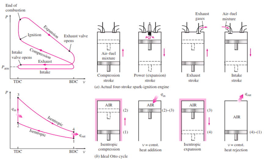
(note that the image below is not done by me, just being used for educational purpose)
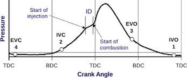
It is advisable for researcher to study the propagation stage which occurs at very small time step. You need to rely on experimental data to know exactly what was the pressure at the instance of combustion. Usually you will find some experimental P-V plots and also some temperature plots in relation to time. Do not assign the cylinders walls a 2000 K temperature, that would create a chemical reaction but only at the walls. Usually the walls contribute in heating up the gas charge, but the main initiator for the combustion is the spark plug . The researcher needs to identify what kind of reaction initiation method is used, for a case of gasoline engine meaning it doesn’t have a spark plug. Due to the high compression ratios achieved before the initiation of combustion there is a big rise in the mixture temperature. In conclusion you are required to add a heat source in the mid-section of the cylinder. The following link shows you how. Remember that the temperature of the heat source should be higher than the walls. So as an example take the heat of the wall about 300 deg and the heat source about 1700 deg.
(note that the image below is not done by me, just being used for educational purpose)
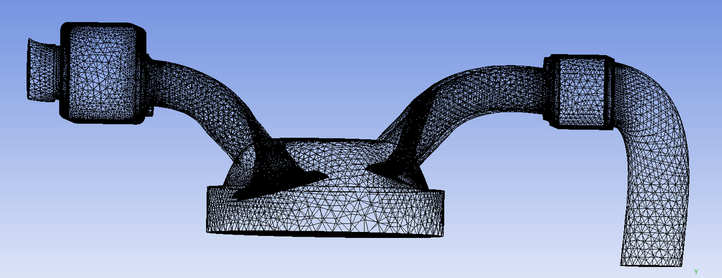
Mesh of a Four Stroke Combustion Chamber Engine
By pressing on the image below you can request the mesh.
Four Stroke Engine Combustion Initiation
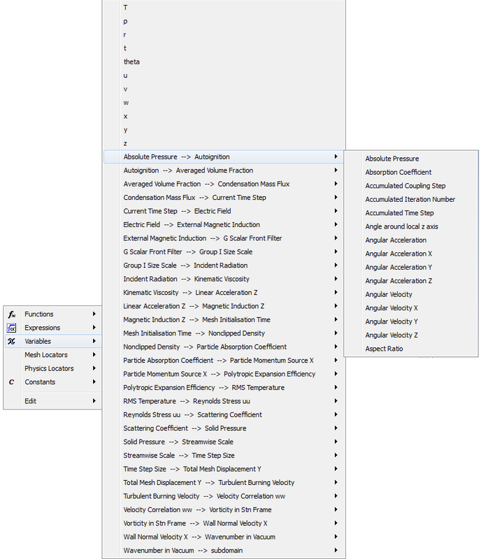
The researcher at some point of the project he will have to ignite his fuel mixture. ANSYS-CFX provides some functions in the Absolute Pressure heading. It is visible that the ignition process can be dependent on the time step, angular acceleration and many other 4 Stroke engine related parameters.
Time Stepping for Reciprocating Engines
Reciprocating engine is a case that a researcher would encounter,the reaction rates are of importance with comparison with the cell size.
Example
Consider having a 4 stroke engine and you want to run a calculation run, knowing that the shaft rotates at 2000-3000 RPM calculate the required times steps knowing that we plan to take 5 time steps per shaft rotation.
Solution
Blade Rotates at and rpm= 2500 (RPM)
We Know that Omega= 2*pi*rpm where Omega has the units of (rad/min)
So the value of Omega in (rad/sec) , reminder that the
Conversion of 2500 (RPM) to (RPS) gives the following value 41.6 (RPS). Meaning that
Omega = 261.7 (rad/sec)
Omega= 2*pi*n = (theta-theta0)/ dt
Based on taking theta0 = 0 (rad)
Based on taking theta = 2*pi (rad)
dt= (theta-theta0) / Omega
dt = 2*pi / 261.7 =0.024 (sec)
This is the required time for a full shaft rotation
If we say we want to capture 5 time frames during one rotation.
We take M = 5
knowing that t0 = 0 (sec)
Time_Duration = t-t0=0.024 (sec)
Time_Step =Time_Duration/M
Time_Step = 4.8e-3 (sec)
Combustion Modelling in Engines
An excellent video done in CFX-FLUENT showing the use of a dynamic mesh:
Multi-step Chemical Reactions Modelling
A video showing how to calculate a multi step reaction by hand. Once the calculation procedure is understood the modelling side become easier.
Recommended Reading
|
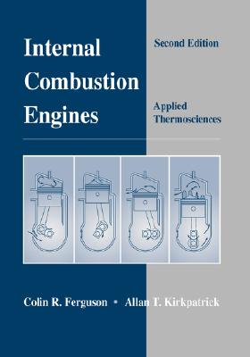
The book called Internal Combustion Engines Second Edition by Colin R. Ferguson and Allan T.Kirkpatrick
|
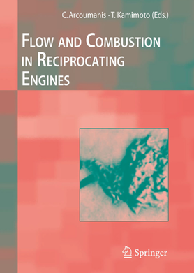
The book called Flow and Combustion in Reciprocating Engines by C.Arcoumanis and T.Kamimoto (Eds.)
|
Unless otherwise noted, all content on this site is @Copyright by Ahmed Al Makky 2012-2018 - http://cfd2012.com
