Mesh
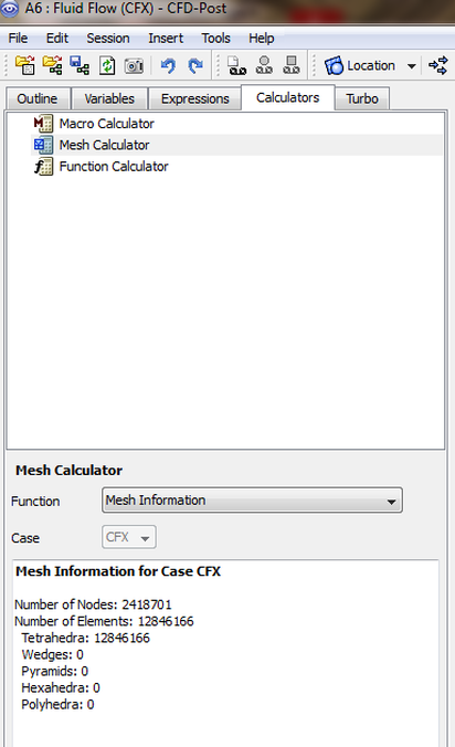
The term mesh is assigned to a geometry that is broken up into discrete number of elements. Several types of mesh can be considered, it all depends on what the researcher selects for meshing method. The following image shows the CFD-Post mesh analysis with the statistical data presnted at the bottom of the image. It might seem to be unnessceary this data but when you have several meshies each meshed with a different method the numbers can be of use. The user will be able to asses how much meomeory is required for the data analysis part of his project.
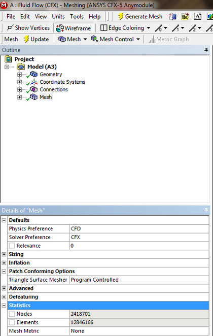
You can also find the mesh details in the CFX-Meshing, the differnce between the previous and this one, is that the meshing one provides you data during the simulation setup process while the first provides you with the information after a calculation is conducted. While during the meshing stage the number can give you hints if the machine can handel these numbers of elements or not.
Good Link relating to mesh : http://www.cs.mtu.edu/~shene/COURSES/cs3621/SLIDES/Mesh.pdf
Mesh Elements
Mesh elements are composed of verticies, surfaces and edges, these mesh elements take the form of a pyramid, hexahedral, tetrahedreal,............. etc. These generated elements details are stored in a vector form.
Nodes
The number of nodes represnts the elements, these elements are composed of several verticies depending on the agreed shape to be used for the meshing process, I presume that the represnted node is locaed in the shape center of gravity need to check this.
Skewness
The skewness of a grid is an apt indicator of the mesh quality and suitability for the assigned application. Large skewness compromises the accuracy of the interpolated regions. The values of skewness should not be assigned randomly, but previous knowledge of the type of discrete mesh geometry is of importance.
There are three methods of determining the skewness of a grid. A Skewness of 0 is the best possible one and a skewness of one is almost never preferred. For Hex and quad cells, skewness should not exceed 0.85 to obtain a fairly accurate solution. For Triangular cells, skewness should not exceed 0.85 and for Tetragonal cells, skewness should not exceed 0.9.
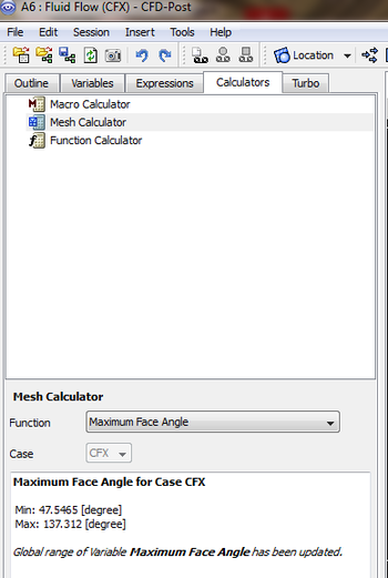
Maximum Face Angle
This calculates the largest face angle for all faces that touch a node. For each face, the angle between the two edges of the face that touch the node is calculated and the largest angle from all faces is returned for each node. Therefore, there is one maximum value for each node. The values that are reported are the smallest and largest of these maximums.
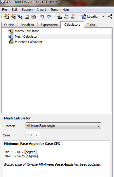
Minimum Face Angle
This calculates the smallest face angle for all faces that touch a node. For each face, the angle between the two edges of the face that touch the node is calculated and the smallest angle from all faces is returned for each node. Therefore, there is one minimum value for each node. The values that are reported are the smallest and largest of these minimums.
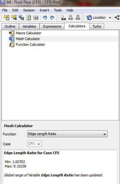
Edge Length Ratio
When studying a mesh element, looking at a specfic face and by calculating the ratio of the longest edge of a face divided by the shortest edge of the face gives the : The Edge Length Ratio.
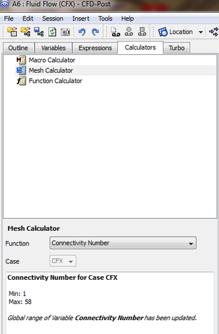
Connectivity Number
The Connectivity number is the number of elements that touch a node, this is a parameter that shows how compact the mesh is at certain regions.
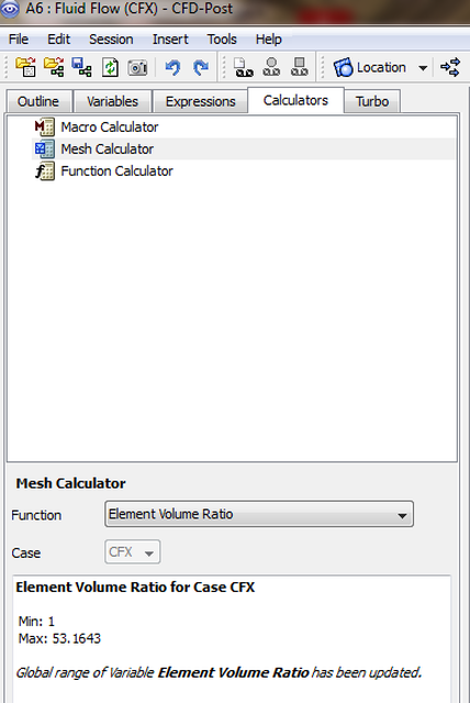
Element Volume Ratio
The element volume ratio will be discussed here.
Unless otherwise noted, all content on this site is @Copyright by Ahmed Al Makky 2012-2013 - http://cfd2012.com
