ANSYS Terrain Modelling
The majority of civil engineering projects require to study a location. The surface location height elevation can be extracted from Google earth after the user has found the location on the Google map.
Using the surface stream lines option for the location the user can extract the required contours of predefined location.
Important notes
1- All tutorial geometries are available: You can contact me by email: almakky@hotmail.co.uk and the mesh will be sent to your email account.
2- Please don’t send me an email asking me to send you tutorials, what is available has been uploaded on the website.
3- I would very much appreciate any feedback about the tutorials, and your contribution will be stated in the tutorial, I plan to update the tutorials.
Using Google Earth
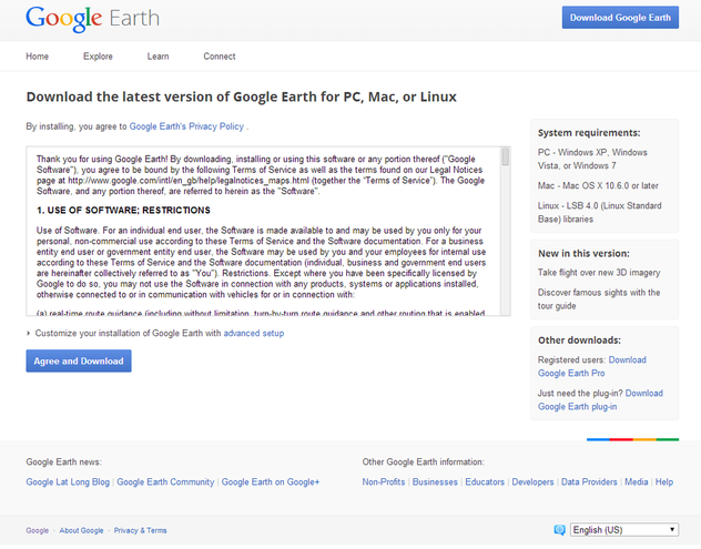
Google earth can be downloaded and then
Google Earth Tools
Several tools can be used to capture the surface texture.
Extracting the Required Contoutrs from Google Earth
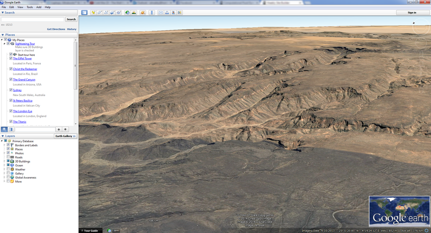
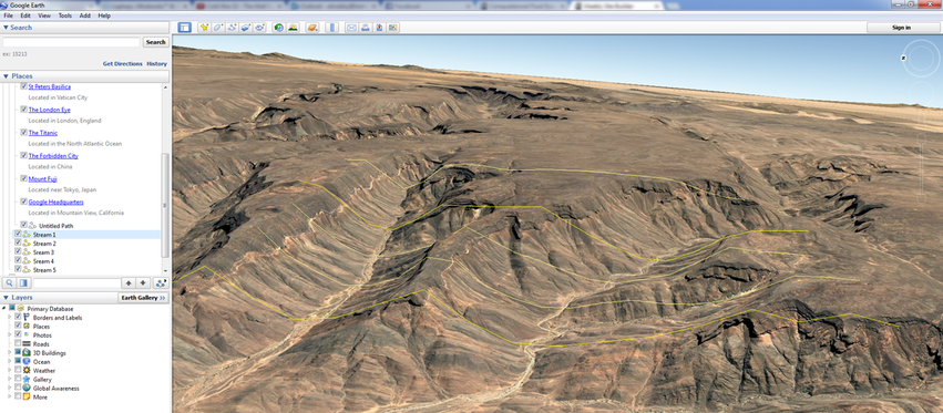
Step 1: Select a location to study. I have intentionally selected one with with mountains to show the big elevation differences.
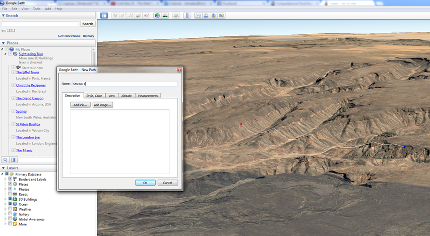
Step 2: Add a path and call it Stream line 1, by specifying the locations of two points.
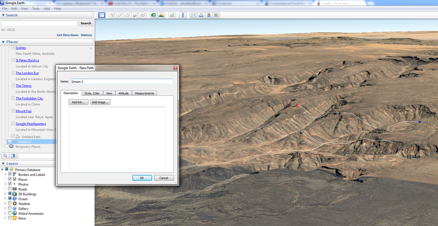
Step 3: Add a second Stream line call it Stream line 3.
Step 4: Add several paths for stream lines until you capture the required curvature for the studied surface.
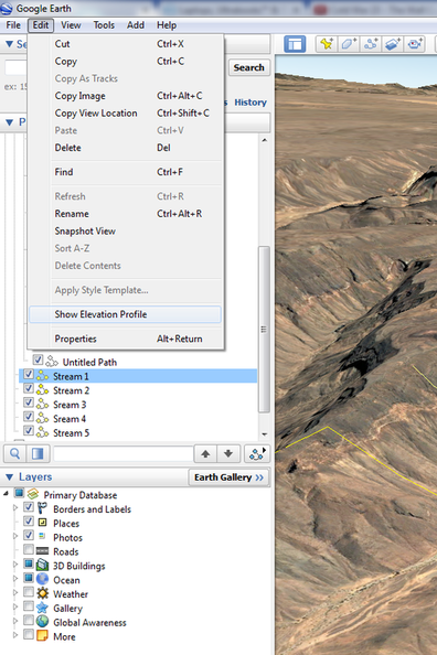
Step 5: Select one of the created streamlines and go to the Edit drop down list and select Show Elevation Profile.
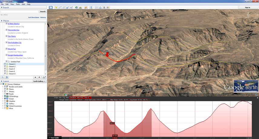
Step 6: Once you have selected the elvation profile you can see the at the bottom the profile.
Step 7: A close up of the captured elevation cross section. You will need to do it to all cross sections to model the surface.
Modelling the Geometry using SolidWorks the Exporting it to ANSYS
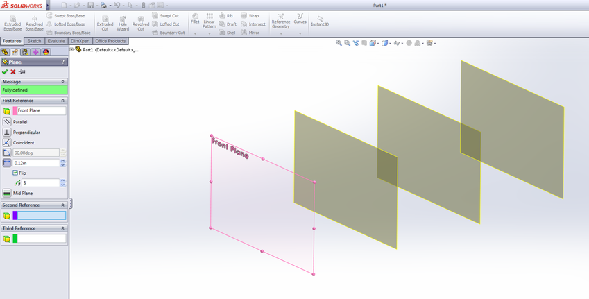
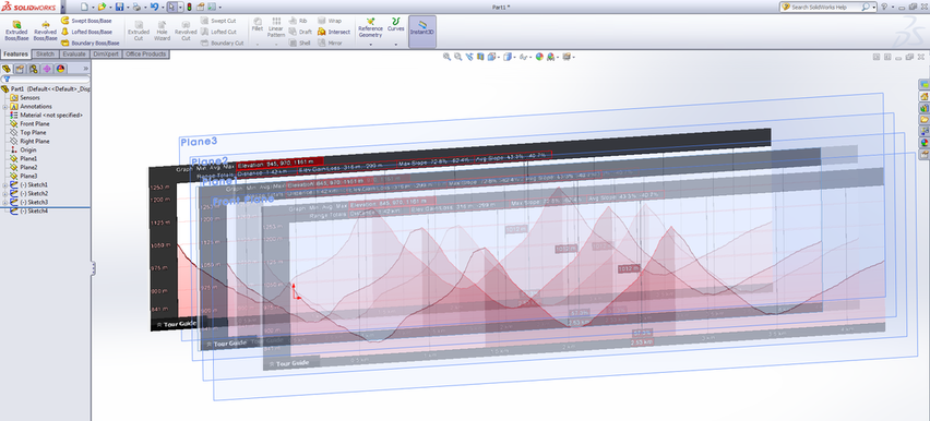
Step 1: creating the sketching planes first
Step 2: Inserting the images and tracing their profiles.
Step 3: After the profiles have been drawn for each sketch plane.
Step 4: Using the loft command and connecting the different profiles together. The following video on YouTube shows the steps on how to use the loft function.
Step 5: Exporting the geometry as a parasolid extension file to be read into ANSYS. This is done by going to the save as and selecting the parasolid format.
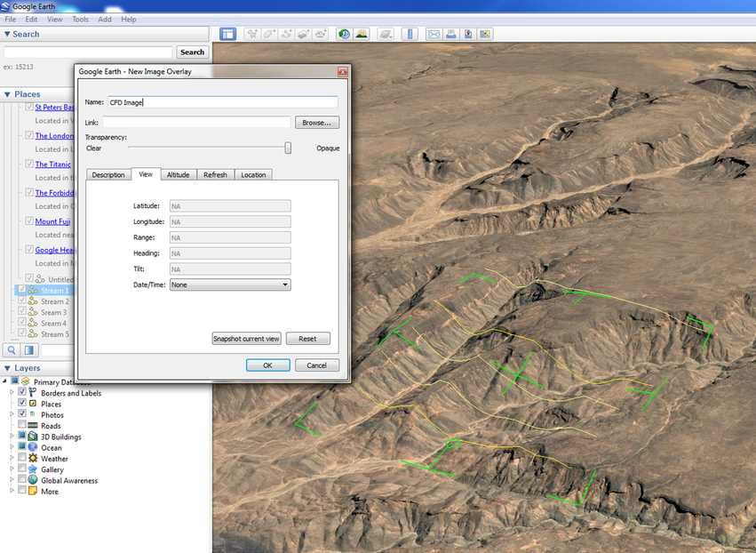
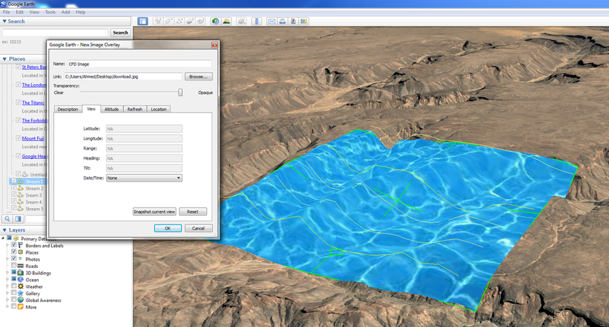
Applying a Calculated CFD Image from ANSYS to Google Earth
Step 1: here as an example a water texture is inserted
Step 2:
Unless otherwise noted, all content on this site is @Copyright by Ahmed Al Makky 2012-2013 - http://cfd2012.com
