Flow Modelling Around a Wind Turbine
The latest new section on my website is the wind turbine one.
Important notes
1- Please don’t send me an email asking me to send you tutorials, what is available has been uploaded on the website.
2- I would very much appreciate any feedback about the tutorials, and your contribution will be stated in the tutorial, I plan to update the tutorials.
1- Please don’t send me an email asking me to send you tutorials, what is available has been uploaded on the website.
2- I would very much appreciate any feedback about the tutorials, and your contribution will be stated in the tutorial, I plan to update the tutorials.
A new blog has been setup for additional comments and to insure interaction between researchers.
Flow Modelling Around a Wind Turbine Tutorial
|
Under Construction, the material is available, unfortunately I didn’t get around writing the wind turbine tutorial which has been requested
regularly in addition to some problems I didn’t get around in solving relating to the tutorial. Wishing you all the best. The following link can be of help relating to wind turbine aerodynamics , the next useful link covers the calculation procedure of a wind turbine Torque.
To calculate wind turbine power output and other important parameters the researcher is referred to the following link. |
Required Geometry for Tutorial One Domain
Click on the image below to download the geometry needed.
Tutorial
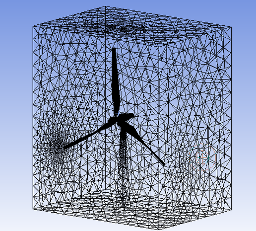
The wind Turbine mesh can be read into Design modeller and can be meshed using the automatic mesh option.
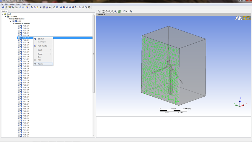
Step 1
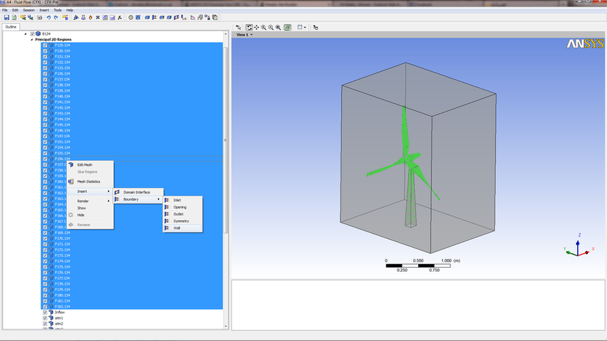
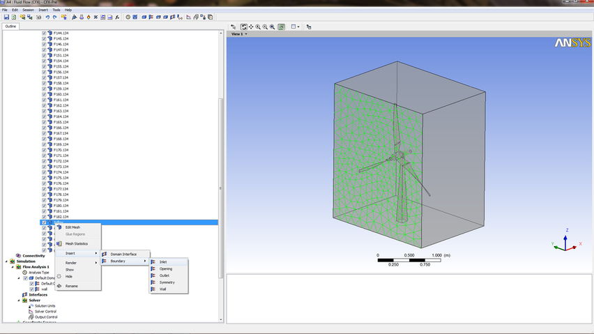
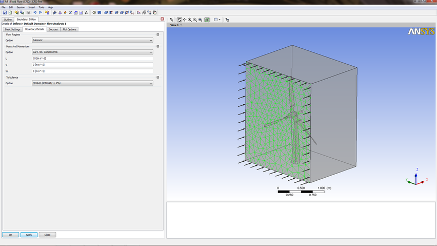
Chose rename and call the surface inflow.
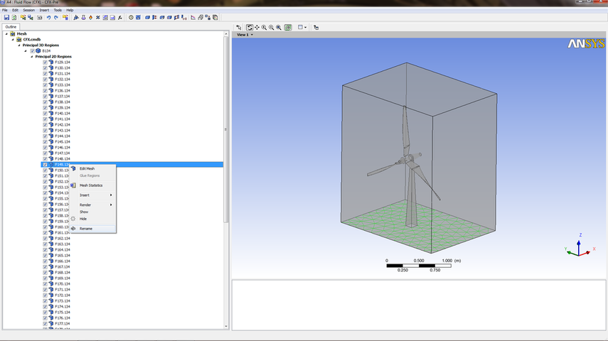
Step 2
Call the highlighted surface grass. This boundary will be applied a wall boundary condition.
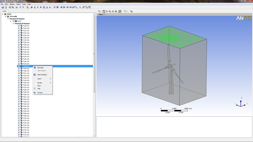
Step 3
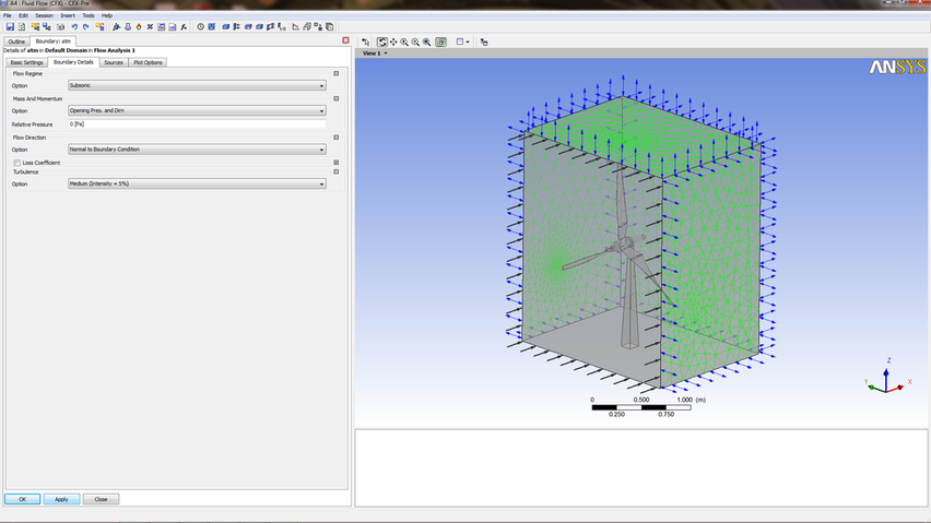
Call the surrounding surfaces atm1, atm2, atm3, atm4 starting with the highlighted green surface, in order for later to apply a pressure boundary condition.
Step 4
The next step is to select the wall boundaries which are highlighted in green, you are asked to enter a name call it Wall.
Step 5
Step 6
Step 7
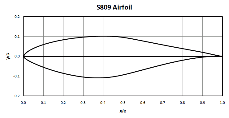
Wind Turbine Blade Profile
There are lots of wind blade profiles, click on the image below to access detailed info
Horizontal Axis Wind Turbine Modelling
Recommended Reading List is to read a reference called Aerodynamics of Wind Turbines by Emrah Kulunk. The mathematical modelling side of the subject is discussed in an excellent manner covering the Blade Element Theory, Blade Element Momentum Theory, Tip losses, Frozen Rotor Condition, Actuator Disc Model and Rotating annular stream tube analysis.
Requirements of the CFD Researcher to Obtain
The following points summarize some of the requirements you as a researcher have to achieve
1- The CFD Researcher has to study specific parts of the wind turbine and seeing how streamlined it is.
2- The CFD researcher has to Monitor the simulation calculation process through the convergence of the solution in addition to decrease the amount of error for the solutions.
3- Deviations between the measured parameter on the test field (or in the wind tunnel) and the used numerical methods occur the researcher has to find the best correlation issues.
4- As a CFD researcher you will need to find new aerodynamic emerging trends that apply to your needs test them through running several calculation trials, then these points are forwarded to the Design team.
5- Depending on the size of the project and how many elements require to be aerodynamically assessed this would require the management of a group of CFD aerodynamicists, providing technical leadership and guidance.
6- As a CFD researcher you would require to make on the spot resources assessment through managing and allocating CFD resources workload for the team and ensuring deadlines are met.
7- As a researcher you will need to find procedures for different aerodynamic solutions for wind turbine parts that deliver performance which fits the requirements of your employer.
8- The working environment should be relaxed more of a family based attitude and care for the success of the whole team is the objective this would lead to new innovations in both aerodynamics and in the use of CFD.
Recommended Book Reading List
|
Recommended reading is the
following book it is called WIND ENERGY HANDBOOK. It will focus on the essential parameters the researcher needs to focus on when studying wind turbines.
Recommended Thesis Reading List
http://veprints.unica.it/84/1/carcangiu_carlo_enrico.pdf
http://clok.uclan.ac.uk/2399/1/CaoH_final_thesis.pdf |
Calculating Generated Turbine Torque
The forces generated around an airfoil are a result of flow fields created between two sides of the turbine blade. The bigger the pressure difference occurring between the upper and lower side of a wind turbine blade the larger the generated force on the turbine blade. You will need to apply contour plots on the turbine surface relating to the forces variable. You will need to look at the regions in a red color and then extracting the value of maximum force acting on the turbine blade and comparing the values with the color key.
Calculating Shaft Load
The researcher will need to calculate both the bending and the shear stress diagrams.
Selecting Shaft Ball Bearings
By Knowing the weight of the turbine, shaft, alternator and accessories you can select through company catalogs the ball bearings that fit the force requirements, remember there are two types of load axial and normal acting force.
Calculating Lubrication Circuit
According to the encountered rotation velocity of the wind turbine results in heat production due to friction, the lubrication oil absorbs this heat and is then passed to a heat exchanger in order to dump that heat into the atmosphere. As a researcher you will need to estimate the produced heat and see if it matches the heat exchanger requirements.
Choosing the Wing Profile
This all depends on the study of the histogram of the occurring velocities on site.
Choosing Gear Box
The selection criteria depends on the generator output power, this means a certain rotation range must be specified to match it with the velocity of the gear box .
Choosing Blade Taper and Twist Angle
Twist angle depends on the type of airfoil used, you will need to chose the optimum angle in between the break down of lift region and zero angle. The twist angle increases as you go further down to the tip of the blade. The reason is that due to central fugal velocity occurring, what can be done is guide the flow along the turbine blade in order to extract as much kinetic energy as possible. The reason for the blade taper is to decrease its mass so that when excess wing loading occurs occurring vibrations due to the generated life can be reduced.
Simulation Validation Techniques YouTube Material
|
A way to validate the wind turbine simulation is to monitor the blade tip vortices kinetic energy along a line in the rear section of the turbine (helical Wake), noting that the line starts a distance ahead of the turbine unbounded inlet section. This is presented in a video available on youtube.
This is to be applied at each time step. Consequently at each time step across the line as the blade tip comes closer the velocity rises being the highest when near to the blade tip. As you move down stream across the line there would be a decline in the velocity. Hence at each time step the velocity profile across the lines starts builds up and then as the blade tipe moves away the profile deflates. |
|
Unless otherwise noted, all content on this site is @Copyright by Ahmed Al Makky 2012-2018 - http://cfd2012.com
