Flow Modelling Using ANSYS CFX around a Formula 1 Car
The latest new section on my website is the following one.
Important notes
1- All tutorial geometries are available on this page.
2- I would very much appreciate any feedback about the tutorials, and your contribution will be stated in the tutorial, I plan to update the tutorials.
1- All tutorial geometries are available on this page.
2- I would very much appreciate any feedback about the tutorials, and your contribution will be stated in the tutorial, I plan to update the tutorials.
A new blog has been setup for additional comments and to insure interaction between researchers.
Tutorial for a Formula 1 Car
Required Geometry for this Tutorial
Click on the below to download the simulation geometry for a half domain configuration. The reason to use half a domain to make use of the symmetrical characteristics and furthermore to lessen the required calculation resources. Watch instance 8:59 in video link.
Click on the below to download the full domain simulation geometry.
Formula 1 Racing Study Notes
The main objective of conducting a CFD study is the following
1- Reduce frontal drag area, by using a more of a curved side view profile, called a stream lined profile, where the air particles path is tangential to the cars surface. This would ensure no negative pressure regions are produced. In general just by reducing the height of the car. That is why racing cars are low in height. Hence that is why racing cars drag coefficient is of importance.
1- Reduce frontal drag area, by using a more of a curved side view profile, called a stream lined profile, where the air particles path is tangential to the cars surface. This would ensure no negative pressure regions are produced. In general just by reducing the height of the car. That is why racing cars are low in height. Hence that is why racing cars drag coefficient is of importance.
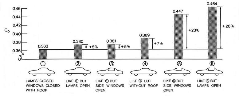
The power of the drag coefficient becomes clear when experimental data starts being gathered, the image below shows the different configuration tested and how that impacted the drag coefficient. (Note the image is not done by me and is only used for educational purpose).
2- Use guide vanes to make the flow stream lined. Another way is by using ducts to guide the flow to internal car cavities in addition to the engine to cool its exterior to the optimum required level in addition to using the air to cool the lubrication oil heat exchanger .
3- Reduce the negative pressure region after the racing car by guiding it in the upwards direction through the use of the rear spoilers, and pushing away negative pressure regions as the develop in the flow, by applying to them a pushing force.
4- To calculate the produced down ward lift if it is enough to keep the car on the ground at different speeds.
5- To check that the water particles on a wet road are directed away from the driver and car. In addition to fix guide vanes on the frontal spoilers each for a purpose. One is to guide the flow to flow tangentially over the wheels. Two to blow the flow generated by the spoilers tips in the outward direction away from the car.
6- To guide the energetic flow from the laminar regions to the negative flow regions resulting after the frontal wheels, in addition to sucking the rest of the region into the two side ways inflow sections situated beside the driver.
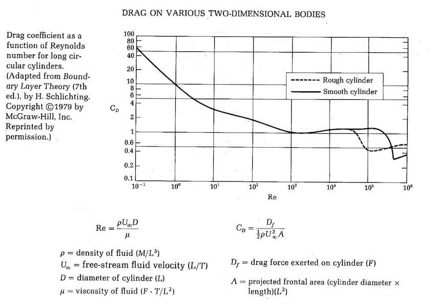
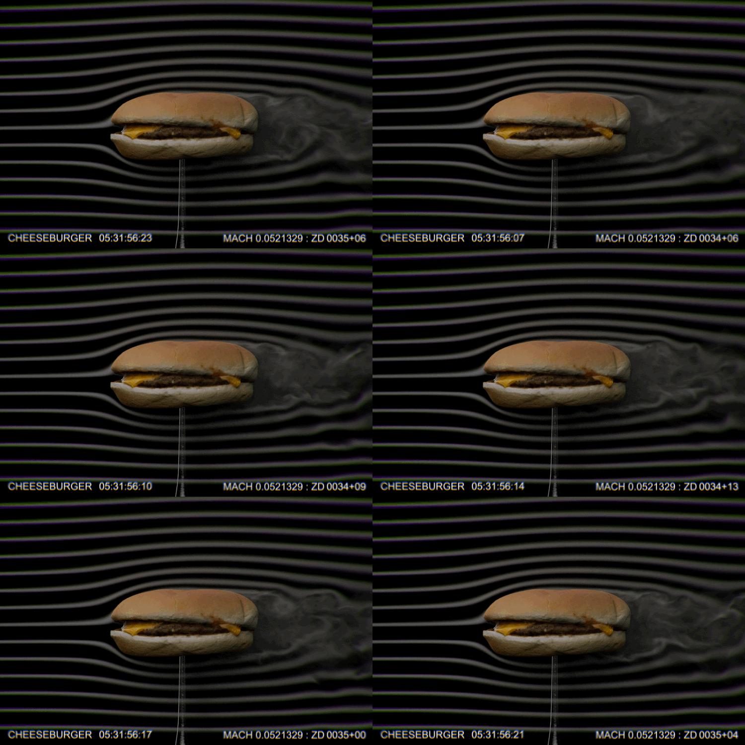
The drag coefficient relationship for a sphere in relation to the Reynolds number. Viscous effects cause flow damping at the cars surface for a small scale car for 1/1000 scale model. While for 1 to 1 scale car viscous effects become less evident. With the increase of the flow velocity the kinetic energy of the flow stream over comes the viscous effects created by the cars shape. Consequently this shows the importance of wind tunnel tests.
Meshing Formula 1 Car
|
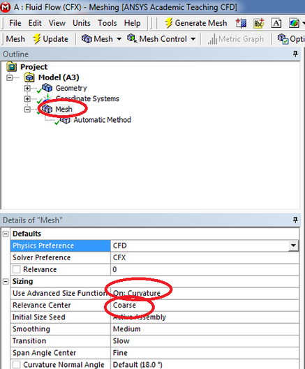
Under mesh select tetrahedral meshing, in the use advanced size function select : on Curvature and proximity.
Finally under Relevance centre: select medium. Simulation SetupThe wheels have to be considered as a rotating solid. Therefore 4 domains need to be modeled and assigned a coordinates system representing the the axis of angular rotation. Remember to apply a ground velocity boundary condition that has the same value as the tangential component of the wheels.
Step 1 Assigning the inflow boundary condition
Step 2 Assigning the wall boundary condition for the car surface
Step 3 Assigning the atmospheric opening boundary condition
Step 4 Running the calculation
|
Requirements of the CFD Researcher to Obtain
The following points summarize some of the requirements you as a researcher have to achieve
1- The CFD Researcher has to study specific parts of the racing car and seeing how streamlined it is.
2- The CFD researcher has to Monitor the simulation calculation process through the convergence of the solution in addition to decrease the amount of error for the solutions.
3- Deviations between the measured parameter on the race track (or in the wind tunnel) and the used numerical methods occur the researcher has to find the best correlation issues.
4- As a CFD researcher you will need to find new aerodynamic emerging trends that apply to your needs test them through running several calculation trials, then these points are forwarded to the Design team.
5- Depending on the size of the project and how many elements require to be aerodynamically assessed this would require the management of a group of CFD aerodynamicists, providing technical leadership and guidance.
6- As a CFD researcher you would require to make on the spot resources assessment through managing and allocating CFD resources workload for the team and ensuring deadlines are met.
7- As a researcher you will need to find procedures for different aerodynamic solutions for the racing car that deliver performance which fit to the requirements of your employer.
8- The working environment should be relaxed more of a family based attitude and care for the success of the whole team is the objective this would lead to new innovations in both aerodynamics and in the use of CFD.
Recommended Reading List
These are some books which are recommended as a reading list.
1- Aerodynamics of Road Vehicles from Fluid Mechanics to Vehicle Engineering. Edited by Wolf-Heinrich Hucho
2- Hucho-Aerodynamik des Automobils Stromungsmechanik.Warmetechnik. Fahrdynamiik.Komfort
2- Hucho-Aerodynamik des Automobils Stromungsmechanik.Warmetechnik. Fahrdynamiik.Komfort
Reading List
Knowing the different parts of the racing car is essential in order to know what requires development and how to do the needed calculation during the design stage.
Making an aerodynamic stream lined car is the objective, the following book exposes the reader to the different aerodynamic challenges in the development process.
YouTube CFD Simulations for a Formula 1 Car
|
An ANSYS-CFX flow Demo video available on YouTube.
It is a good tutorial showing how to assign the proper boundary conditions the car surface and rotating wheels. In addition to later assigning the mirror option for the data analysis part of the project saving some calculation time and the allocation of hardware resources. |
|
|
This video available on youtube shows the data analysis part of a CFD project which is focusing on the pressure parameter. Because it plays a major part I the aerodynamic assessment phase of the project. Hence the parameters of study usually are surface pressure contours, pressure sweep contour plane, stream lines , vortex core regions. stream line distribution scan on the vertical axis.
It is noticeable that the sharp edges located on the surface of the formula one car are sources of turbulence shown in a green a foam. The green foam is a function from the derived vortex core variables. These vortex foam regions are mainly negative pressure regions that are either regions of flow speedup or regions of stagnation. |
|
|
Commenting on a video available on youtube. The power of using stream lines is that it captures a flow pattern at an instance of time with the option of showing the velocity vectors of the flow moving tangentially to the streamlines. The color of the stream lines shows regions of high and low pressure. The colors applied to the stream lines can give an indication that the results are right or wrong.
|
|
Unless otherwise noted, all content on this site is @Copyright by Ahmed Al Makky 2012-2018 - http://cfd2012.com
